Friday, August 23, 2019

Trying my hand at scenery

It's far from finished but I thought I'd document my first attempt at doing some scenery for the model railway. The thing is I was never "good" at art at school, mainly because of my lack of colour sight always making me think I couldn't "do" art. But that that doesn't stop one being creative and although my art teacher could not comprehend the colour issue, I've found other ways to be creative that don't involve distinguishing red from green or blue from purple.

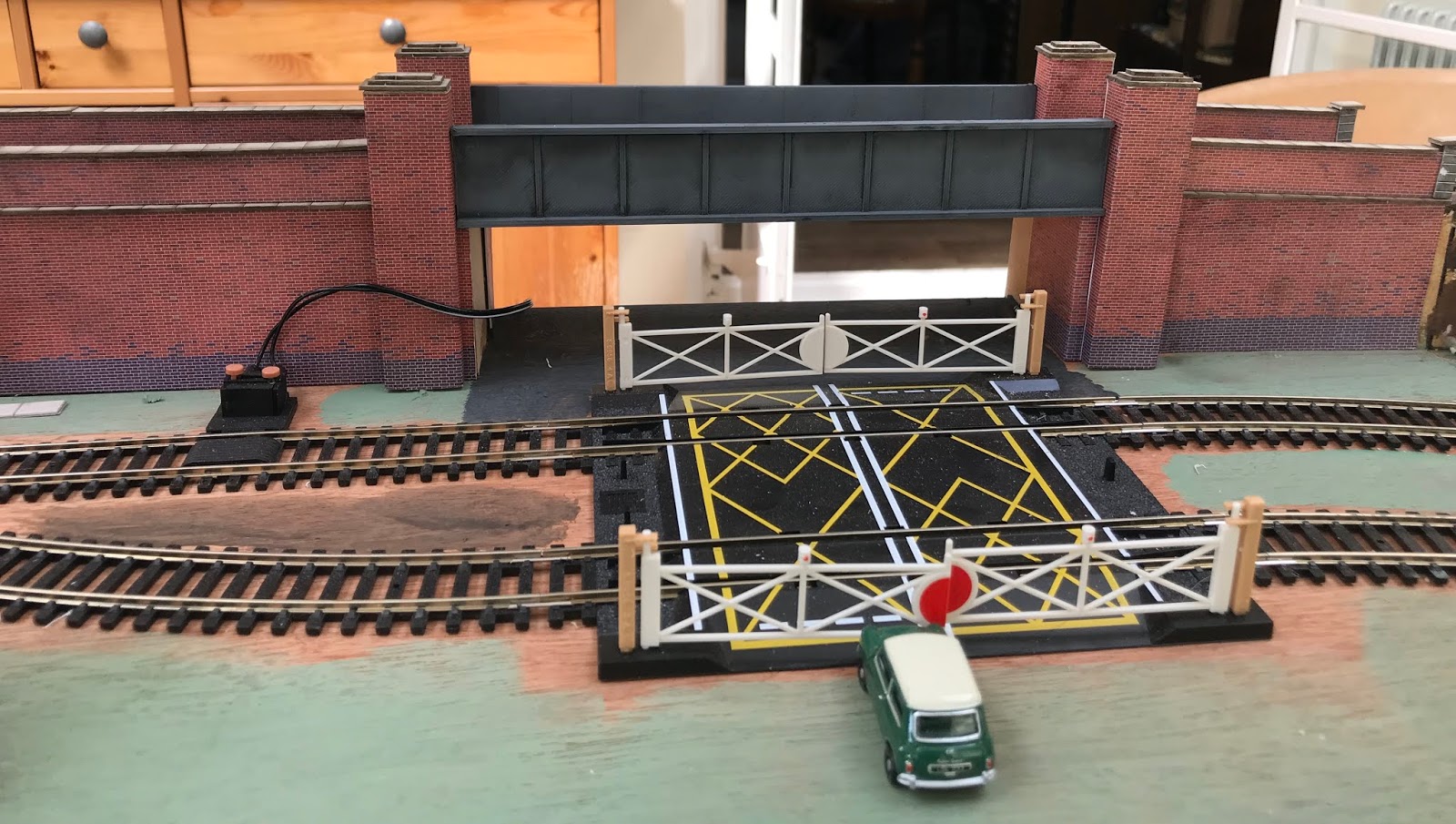
Adding scenery to the layout was always part of the deal. It began with some of the buildings about which I have already written. But what about grass and trees etc? Well, here's the progress so far.

It still need more grass adding, but I'm waiting for a better state grass applicator to arrive. For those who don't know, static grass doesn't refer to a lack of movement but the way it is applied. It uses a static charge to make the grass fibres stand up. You can do this with a plastic bottle, but that doesn't seem to have worked particularly well.

I've used a process I saw in a video by Kathy Millat, although the layering spray I bought was the same product it was not in the spray can but an aspirating type bottle which may have made a bit of a difference. I also used a puffer bottle rather than the electrostatic applicator which I have now ordered to try on the next area.

The trees came ready made from Model Scenery Supplies, as did much of the static grass. I built the embankment from PIR insulation board (Cellotex in my case). It's easy to carve and shape using a sharp kitchen knife.

Small gaps were filled with decorators caulk. On reflection a more rigid filler might have been a better choice but this was what I had lying around in the workshop.

Once that was all dry we covered it with strips newspaper and used standard PVA glue to fix it all in place.


 I wasn't too worried about making it super smooth because that wasn't the finish I wanted. I wanted something uneven and less cultivated looking.

Once dry it got a coat of poster paint to give a soil like base. Even at this stage it was looking okay although there were a few cracks that needed sorting out. I painted a few area white and grey using acrylics and washed them with a black wash to make bits of chalk face show through.

Some got covered up with grass when I forgot to avoid them with the base glue and layering spray!

Which brings me to the grass application process. As I mentioned, I didn't;t find the puffer bottle that easy to use. I ended up spraying grass fibres all over the place. That's not a big problem, but I did feel that it made getting the stuff in the right place a bit of a chore. I also found that the base glue went off very quickly. Perhaps the painted paper absorbed it too quickly and Male a base coat of PVA to seal the surface first might have helped.

In the end I'm quite pleased with how it's turning out. Having added some line-side fencing and a few tress has made this corner of the layout really come to life.


Tuesday, August 20, 2019

Building a bridge

 Sadly I didn't take any pictures of the process of building the bridge. A bit of an oversight given that my plan was to document the process!

Prototype bridge
It started with a simple prototype made from from 6mm MDF. Nothing more that a couple of supports and the flat bed for the track.

Once I'd figured out the height I built the bridge and added the side sections, all made from MDF.

The girders were 3D printed, primed in grey and then painted with a black acrylic wash to make them grimy.

With the girders superglued in place I set about building the walls.

These are simple card construction. The retaining walls are about 7mm thick and made from two layers of 3mm card and between two layers of brickwork card (Metcalf again). They are actually from the platform kit

I applied the red brick to the main walls first and then added the abutments.

Prototype Abutment
These are made from more MDF. I was going to 3D print them but MDF was quicker. This was a card prototype. You can see the L-shape, the shorter part sitting facing towards the track.

The retaining walls were glued to a strip of stone capping from another kit and the glued in place with the capping overhanging the retaining wall. I thought this added depth and gave it a more authentic look. They were capped off with more stone and one side I went for a slopping finish and the other has a stone end pillar.

The end result is quite pleasing and once again shows that model-making isn't as difficult as it might look. I'm still learning better ways of doing things, but as that say, this is my model railway and the only person I really need to please is myself.

Monday, August 19, 2019

A 3D printer? I can't see the point of one myself!

Well actually I can! It's a pain sometimes, but a 3D printer is a real bonus when it comes to developing my model railway. Originally I bought one (Creality Ender 3) because I wanted to explore the world of 3D printing. I had an idea and a 3D printer was an obvious part of the solution to the problem I was trying to solve.

I started to play with some design ideas for the workshop and then when the model railway began to take shape it really came into its own. I've printed parts for models (doors and roof vents for example), small items (milk churns and oil drums) and trackside fencing. I've also printed a church, chimney pots, stove pipes, bridge sections and garden sheds. Quite a collection.

Some I've designed myself, some I've downloaded from thingiverse. Here's a little gallery of some of the things I've printed.
Chute

Stove pipe and roof vents for disused carriage


Country Church

Chimney stack and doors. 

Oil drums and milk churns

Saturday, August 17, 2019

Small Factory Unit Build

When I printed the church there was a large piece of waste from the the supporting structure the 3D printer produces to support the overhanging parts of the print.

Initially it was head for the recycling bin but then I thought I must be able to do something with it. So it sat around for a while and then I thought about Turing into a building of some sort. I settled on a factory and began to work out what to do.

The first thing to do was to glue the two pieces together to give the basic shape of a building with a chimney.

Most of the factories I remember from my childhood had whitewashed windows. To make these I decided to paint the window area quite roughly before adding the walls with window cutouts.

I used some Metcalf red brick card and wrapped the building. On the chimney I made a layer of engineering brick and then overlaid the join with some roof material that came with the brick card.
A factory obviously needs doors and a roof. I'd bought the rusty corrugated panels and roof lights already because I wanted to use them on the aggregates works. On that build I used superglue but it wasn't the easiest way to glue them place (although they are fine). This time I tried epoxy resin and that has worked quite well and it has the advantage that you don't accidentally end up sticking your fingers together!

A bit more 3D printing and we had the chimney top and some doors.

To finish off I added some barge boards and some guttering and a downpipe. A little more weathering and this is how a waste piece of plastic became a factory.


Friday, August 16, 2019

Finishing off the aggregates works

So  the rusty metal panels arrived and have been fitted along with a roof to complete the building that has become an aggregates depot.

I did say that we were adding things that connected with out life and this has been named after our two grandsons Tobias and Ben.

I might add a second sign above the double doors, but apart from that it's finished.

I need to develop the area around it now-paint the base and texture it, add a few bits and pieces like some ladders and maybe some scrap.

We shall have to wait and see.

The next building project is to make use of the support structure left over from the 3D church print. It seems a waste to throw it away, so it's going to be turned into a small factory unit of some kind.

I'll use more of the corrugated panel for the roof and add some skylights. I'll print a chimney top and some doors to give it some depth.

In between finishing off the works I made a start on the platform for the station. I've ordered a station kit, but it will need a bit of adapting. Either that or a complete rethink if the station position which in turn might make some changes needed to the layout.

We've also had two trains running at a time which is quite exciting. I'm yet to really get to grips with how to wire the whole thing, but I've got a couple of controllers and each is connected to a loop of the track so we cans ee them running.

Here's a short video of it all running. It's oddly satisfying to see these two small trains going round and round in opposite directions!


Wednesday, August 14, 2019

Battered old fruit wagon

Being new to this whole model-making malarky I've been trying out various kits and model making processes.

In the last post I talked about card kits, self build and 3D printed. This one is a laser cut kit made from both card and 3mm thick MDF. It's very straightforward to build and is just the wagon. I decided to make it a repurposed wagon, doubling as a workshop or stores-I haven't decided which just yet.

The card panels lack definition and the lines for the doors have all but disappeared under the paint. I don't have a steady enough hand to pick them out with a fine brush, but I might be able to use a pencil the create some false shadows and give the side panels a bit more depth. If I try that I'll apply a fixing coat to seal the finish.

The kit is just the body of the wagon. If you wanted to run it you would need wheels etc for it. Any extras like the vents (3D printed from my own design) or the chimney (again a 3D print) have to sourced for elsewhere.

I'd certainly consider using one of these again, but at the moment I think to Metcalf kits are the best I've tried. Then again they are for buildings so comparing a wagon model to them isn't quite fair.

What goes where?

Building the model railway is coming along slowly. I never saw it s a weekend job but rather a 3 or 5 year project. Having never done anything like this before, getting a sense of scale is quite difficult. how big are the buildings? What does a bridge look like at 1:76 scale (I'm building in 00 gauge)?

With most of the track down it was time to build something and see what it looked like. Our first building was the signal box. It's made from a pre-cut card kit by Metcalfe's.

Here it is in its almost finished state. Since this picture was taken I printed a chimney for it and there were two other buildings in the kit, a line side hut and a small shed-like building.

The kits are fairly straightforward to put together although you do need to take your time and separating the parts can be a bit tricky. You need a good sharp modelling knife and a lot of patience.

The next idea was to try something using off cuts of mdf that are lying around in the workshop. The plan with the layout is to include things that connect with the family and with things we've done, places we've lived etc.

Again it's not quite finished, but here's a picture of the progress on my first scratch built model.

I'm waiting for some rusty corrugated panels to arrive in the post for the top section. This is a mixture of bits, some printed some card and some mdf. The brickwork is printed card glued to the main mdf structure. The chute and sliding doors are 3D printed. The aggregate is model railway ballast and the coping around the top of the wall is 3mm thick card.

I've also tried to weather it using acrylic paint. The brush is dipped in the paint and then moist of the paint removed before brushing it randomly along the edges and around the walls.

Once it's finished I'll try and post some better pictures.

My third building was a download kit that you print and then glue to card. It came from Scalescenes. They have a free kit for you to try so I downloaded that and gave it a go.

Here it is in the foreground. The kit is a more of a challenge than the laser cut kits, but if you make a mistake cutting something out, you can always print another version and try again. It's also now got a chimney courtesy of the 3D printer.

The 3D printer has also been to use for another model. I downloaded a church from thingiverse. It took nearly 3 days to print, but even then the relative cost when compared to kit was very good.

It was also the first time I've painted something. Not being colour sighted makes painting a challenge, but this was a grey stone building so hopefully I'd be okay!

It's turned out quite nicely. It was primed using a spray primer from Halfords and then painted with the acrylics. The final stage was to use a black wash to give it some depth.


So there you have it. Different ways to create building for the layout. I'm not sure any is better than another, they all have a place. Mixing the forms works well. But that's not unexpected.

I'm currently working on a bridge and I've just built a fish wagon! Pictures to follow!

Friday, August 09, 2019

Building a simple turntable for painting models

I'm not much of an artist but one of the things that I need to learn is how to paint and weather models for the railway. To make it easier a small turntable looks like a useful item to have. Now you can of course go out and buy one but I've got a workshop full of scraps of wood and stuff so I thought let's make one.

It's a simple enough design-a circular table on a square base. Both are made from 18mm ply that was lying around the workshop.

Cutting the circular turntable was interesting. I decided to do it on the table saw. I'd seen someone do this and thought I'd give it a try. It's fairly straightforward and produced a really good cut. I could have used a router and circle jig, but this was quicker to set up and do. you just have to be steady and not try to do too much too quickly. I have a 12mm base that sits in the mitre slot and I simple screw fixed the blank to it cutting off the corners and gradually cutting smaller and smaller pieces away until I got the circle.

The square base has a bolt through it to provide a spindle for the rotating table. It's held in place with a counter bored nut.

The rotating table has another counter bore into which a bearing has been pressed. The bearing is for a skateboard and is about 20mm in diameter. A washer over the nut provides a small amount of separation between the table and the base.

Because the bolt head isn't recessed into the base I glued and pinned four triangular feet to it. These were scraps from something else I made recently and they are 9mm ply.

I then put a liberal coat of wax on the base and the turntable surfaces that meet just to help.

I made a second one using just a screw through the top and washer between the base and turntable. This works okay too.


Saturday, August 03, 2019

Inside to outside

Having been away on holiday I got back to testing bits of the track on our model railway. There are some issues with derailing rolling stock through the points, but I hope to get that sorted out as I finish laying the track and making sure it's as smooth as possible.

One of the common solutions to rolling stock derailing is lack of weight in the wagons and carriages. Adding the right amount of weight should help keep the trains on the tracks. We shall have to see! Another issue can be the play in there wheels. If there's too much (more than 1.5mm) the wagon can jump the tracks as it goes through a set of points. So there are a few things to look at.

Having connected up all the track I ran both the freight train and the passenger train through. The passenger train managed it better than the freight train, but both need attention.

Here's a short video of the Flying Scotsman going from the inside track, around the centre loop and up onto the outer inclined loop:


Friday, July 26, 2019

Testing the incline

Having positioned the inclines and begun to lay the track them, I thought it would be a good idea to test a locomotive on it. Given that the typical kits have a 4% incline and I've gone for 3% it shouldn't pose a problem, but I wanted to test it to be sure.

As you can see, the small loco with a light load easily made it up the slope. Now all I need to do is complete the track laying and then I can move onto wiring and control.

The incline rises 50mm over 1500mm. I'm tempted to build a 4% version just to see what happens, but then again it works so why fiddle with it! Mind you, all I'd need to do is put a 10mm spacer under the high end. Hmm. Hold that thought.

Tuesday, July 23, 2019

A new project

For quite some time I've harboured the ambition to build a model railway. Well the day has coke to make a start. A few years ago Anne bought me a basic oval (The Flying Scotsman) and in there last couple of weeks we've made a start on developing a model railway.

Here's the beginnings of the basic layout for the track:

 It's a fairly simple series of ovals with the outside one rising to go over a bridge. The base is made of three sections each about 1200mm by 660mm so that it can be stored away in a cabinet (yet to be built!). The inclines have been a challenge to think about. Firstly you need to get the gradient right. From looking around the 00 gauge loco's are able to climb a 4% gradient. I've gone for around 3% (50mm over 1500mm). Once I've got some track on them I can test them out to see if it's ok.

To make the inclines I used 3mm hardboard (I used some thin ply first time round but hardboard is a bit easier to bend into shape).

I made a simple tapering jig for my table saw and cut two at a time.


Rather than do a lot of maths I made the outside incline and then used an off cut to measure the inside because it's obviously shorter around the inside than it is around the outside!

I cut a whole series of pieces to space the two sides apart and glued them in place before creating a card template of the curve.

I then used the template to trace the shape onto some thin ply and a jigsaw to cut the pieces. They don't need to be perfect because they will be landscaped at some point.

The next step is to glue all the pieces together and then decide on their final positions. Hopefully all the track Weill be connected so that trains and rolling stock can be moved from track to another.

 There's also room for extension at either end if and when we want to add say a boat yard or factory. I'm making provision for extra track by adding some points in strategic places.

Monday, April 15, 2019

What's it like being a sports parent?

To be honest, I don't know, but from my limited experience of being a tennis coach I've seen good and bad examples. I've often thought about what I would like parents to do and how I'd like them to behave.

These are some of the things I'd tell parents if they actually asked me!

Life is never going to be the same again! 

You will spend time, energy, effort and money supporting your son and daughter as they learn, train and compete. You will be transport manager, kit supervisor and supplier, and many other things. You will watch from the side-lines and, if you care about them, you will probably live every moment, play every point and experience every high and low of their matches.

So how can you best play your role in their journey?

Here are a few things that we hope will help:

1. Remember they are the player, you are the parent. You cannot and should not try to live out your sporting dreams through them. Let them play. Encourage them. Praise them. Tell them you are proud of them.
2. Be the parent not the coach. Coaches see things you do not see. They understand the process of learning and developing. Let them do their job. Ask questions by all means, but trust them.
3. Be positive. No player needs to be told when they have played badly or hit a poor shot. Don't let your frustration show. You can be sure that the moment you have your hands in the air in despair, that will be the moment they look across to where you are sitting.
4. Don't let them think they are ever letting you down because they aren't winning.
5. Ask them how you can help them.
6. Chart the matches: This is helpful to the coach when they get on the practice court and it gives you something to do.
7. Don't offer rewards for winning. This just adds pressure, especially if the reward is highly desired!
8. Avoid analysing matches straight away.
9. If you're not at the match then don't make: "Did you win?" your first question. Ask them about the experience of competing; ask them about how they felt they played.

I'm sure there are more things I'd want to add to list list, but that will do for now. 

A useful resource is this little book: Conversations for the Journey. It's available from Non-Perfect Dad. It's 64 pages long and contains a series of questions creative ways to handle conversations with your sporting child in a positive and affirming way.

Thursday, March 07, 2019

Extension to my MFT-style bench

I decided to build a small extension for my MFT-Style bench to support the waste side material so it didn't just fall on the floor after cutting. It's a really simple build but as ever there is quite a lot of designing and redesigning along the way to make it work how I imagined it.

The extension is very simple:
 The piece of MDF that forms the top is just something I had lying around and was about the right size. It sits in a rail made from a piece of softwood, also found lying around. The rail is made on the table-saw. I am so pleased I bought it!

There are a couple of supports and a strip of MDF that locate the extension in place. You can see these in the picture of the underside.

The timber supports have a rebate at one end that sits in a matching rebate in the vertical part of the rail.

My idea was to make this something I could put in place when needed and store out of the way when not needed. The simplest solution to how and where to store it that I could come up with was to make a couple of brackets and screw them to the legs of the bench on the end where the extension will be used.


It's out of the way but easily accessible and right where it needs to be.

I might yet build a slightly longer (or should that be wider) knock down extension that attaches in the same way but has its own fold out legs to support the other end.

The challenge as ever is where to stop it if I make it.

Monday, February 25, 2019

Building my new benches

By now it must be obvious that I decided to sort out the garage and make it more of a workshop. My old bench that I built many years ago had to be easy to set up and take down because I worked outside when the weather permitted. Now I had the garage space in which to work and it was just time to build a new bench.

The outside wall of the garage has pillars 1600mm apart, so I decided to build one new bench to fit between two pillars and then another bench the size of the MFT top to fit in the gap the other side of the pillar. I then decided I'd build my router table into the bench using the cabinet I'd built previously.

Here's a view along the length of the benches.

Overall I now have around 3M of bench space, 720mm deep.

Each bench has a simple frame made from stud timber available at my local DIY store (B&Q as it happens) and the bench top is 18mm MDF to match the MFT top. Once built they are finished with wax, although the router section is finished with 3 coats of a water-based varnish (purely because I wanted to try a different finish on the MDF when I made it).

The bench frame was constructed as two rectangles and the legs were fastened on the inside squaring it up as I went. A bottom shelf adds to the rigidity of the bench and it's certainly rigid and strong.

You can see how simple the frame is here. The bottom shelves were made from whatever I had left-over. This one is some OSB, the other bench has some 18mm ply I picked out of the off cut box at B&Q. I'm very grateful to whoever it was that didn't want the off-cuts, I got almost a full sheet of good sized pieces!

The work bench has a small vice attached, and I am planning to build a better woodworking vice for it. I also drilled some 20mm holes in the top so that I could use the bench dogs and clamps with it as well as the MFT style bench.


The MFT has a piece of aluminium extrusion on the front edge set just below the height of the top. I could have used T-track, but I bought a piece of extrusion to make a fence and decided to buy a second piece for the front edge. T-track would have been more flexible because it would take the track clamps. The extrusion is primarily intended for building CNC machines, but it makes a great fence.

 Here's the MFT with the fence. You can also see the bench dogs in their holder on the wall behind and attached to the fence is the flag stop.

So far it's all proved very useful. The built-in router table works okay. It has two slots for its fence. The fence has a couple of carriage bolts that drop through holes in the top and run in a couple of grooves.

So, how much did it cost? The timber was probably around £40 for the studs and a sheet of OSB, oh and there was the MDF for the router table and workbench.

The MFT top was £36 from CNCDesign and the extrusion was £34 from Ooznest for both pieces. There bench dogs came from Benchdogs as did the flag stop and the fence dogs. They came to around £68 in total.

The. various jigs and things I've made to go with the MFT are all made from scrap. The only thing I had to buy were some nuts and bolts to use with the track. A fully kitted Festool MFT3 comes in at around £600 new, £300-400 without the fence and guide rail extras.


Saturday, February 23, 2019

Vertical clamping stops

 The aluminium extrusion on the Festool MFT allows you to use the Festool (and similar) clamps to hold material vertically. There extrusion I've used doesn't have a wide enough groove, so I had to come up with another solution.

Here are my original prototypes. The design was simple enough: a "plate" that sat on the front of the rail with a piece of mdf above and below the rail to help secure it in place.

An M5 bolt and T-nut secure the stops to the track and a 20mm hole allows the the clamp to be used with the block.

When I tried to use them it became apparent that they needed to be wider so that the clamps worked effectively. The central hole simply didn't work, so I drilled out another hole nearer the edge and cut away a notch to allow the clamp to have more surface on which to bear.

The other problem was that the clamp would turn in my hand and that made using it tricky. I added a small block but that didn't really help. So I came up with another design.

This time I cut a groove in the back of the face plate. I also made the plate wider. I thinner cut a notch to allow for the slight inside curve of the clamp and then used a small piece of 6mm material (the main components are 18mm mdf) to prevent the clamps falling out the back of the groove and to limit any tilting of the block. Probably not necessary because the nut and bolt pull the plate securely onto the rail.

Another groove towards the top allows the clamp to be placed in two positions. The two blocks are made as a pair-left and right handed-and work really well.

Because of their design, these clamping blocks can be used as stop for other things used with the bench.


Wednesday, February 20, 2019

Workshop update: MFT Track Saw

As part of the process of reworking the garage/workshop I decided the explore the world of the MFT (Multi-Function Table). Those familiar with the term MFT will immediately think of Festool and how expensive their MFT can be. I'm not complaining about the cost of Festool kit. As far as I can tell it's worth the price, but for me it's out of my budget.

As I began to build my new bench system (something I haven't actually documented-a job for another day maybe) I decided to look at the concept of the MFT and see what I could incorporate in my design. I stumbled across a company that CNC replacement tops for the Festool table for around £40, and via various other searches and links I found a company who make bench dogs and flag stops etc for MFT's too.

So I built a simple bench using the MFT top and added some aluminium extrusion to the front edge and used another piece for a fence. I'll do some photo's and a post about that. I bought a track saw and using the bench dogs and the fence I now have a really useful track saw station and a clamping surface that is very nice to use indeed.

To support the track I made a simple support that rides on the front rail and locks in position with a couple of T-nuts and bolts. At the other end is another piece of MDF so the track is supported at both ends.


I made it from 18mm MDF because that was what I was cutting, but I also cut 6mm, 9mm and 12mm material, so unless I put something under the work piece the track isn't in contact with the stock. So I decided the make a 6mm and 9mm version.

But I didn't want to have to make more knobs and anyway it's quite fiddly getting the nuts into the track. So I made my 6 and 9 supports without the bolts and made some simple stops that run in the track and lock the support in place.

 I cut some pieces of MDF and ply to use at the other end of the track and now I have a couple of sets of supports. A couple of extra bits of 6mm MDF turn my 6mm support into a 12mm support and there are a couple of other bits of thin ply that can be used to raise the track around 5mm if needed.